GT68R Color Paperless Recorder
GT68R Color Paperless Recorder
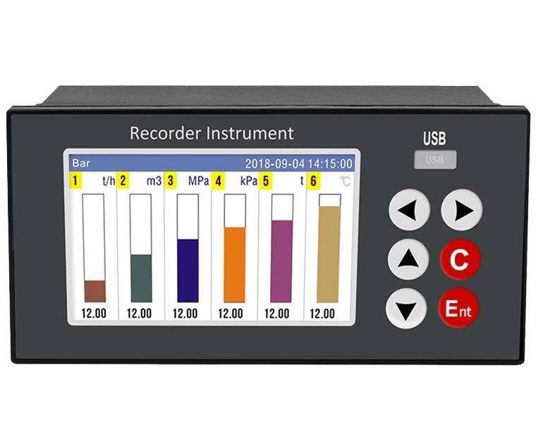
Paperless recorder, 6-channel universal input, 160*80 panel size. Supports industrial signals such as current, voltage, thermocouples, RTDs, and frequency (customizable), enabling signal data recording. The recording interval is as short as 1 second, and historical data can be quickly transferred via a USB device. Channel data is displayed in real-time in numerical, bar graph, and curve formats.
Product Features
High-definition color LCD screen, 4-inch 800*480 pixel resolution
Full-range 0.2% high-precision signal acquisition
6-channel universal signal input, 6-channel relay output
2-channel current transmitter output
2-channel 24V DC power distribution
1 RS485 communication interface
Built-in Chinese and English languages, freely switchable
16MB memory, 900,000 historical records
256 alarm, power failure, and operation logs
USB 2.0 high-speed data backup interface
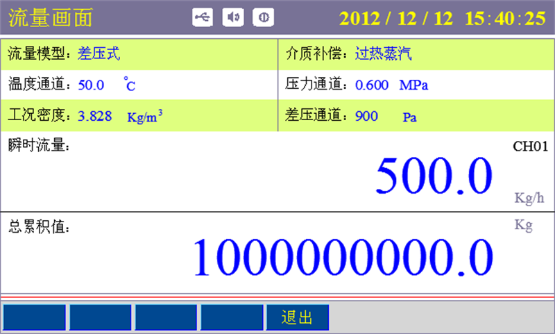
Traffic Interface
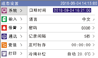
Group interface
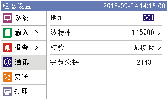
Communication interface
Product Advantages
Hardware configuration adapted to industrial needs: The 6-channel fully isolated design prevents signal interference and ensures measurement accuracy, meeting the needs of multi-parameter synchronous monitoring in industrial scenarios; 128Mb large-capacity memory can store 900,000 records, satisfying long-term data retention requirements; abundant interfaces (USB, RS485, RJ45) support rapid data export and remote communication, compatible with industrial automation system integration.
Functional design balances practicality and flexibility: Multiple interface display modes meet observation needs in different scenarios (e.g., digital display/curve for real-time monitoring, historical curves for data review); four-level alarm mechanism with relay delay and hysteresis settings allows for precise early warning based on actual needs, reducing false alarms; full-dimensional configuration functions support users to customize parameters according to specific application scenarios, adapting to different signal types, measurement ranges, and communication protocols.
High ease of operation and maintenance: Clear button logic and intuitive interface switching allow for easy operation without professional training; one-click data export via USB drive simplifies the data transfer process, and PC software supports subsequent data analysis; the targeted troubleshooting guide quickly identifies common problems, reducing operation and maintenance costs.
Detailed explanation of key technical parameters
| project | Specification |
| Instrument Dimensions | Panel size: 160*80mm, mounting hole: 152*76mm |
| Instrument Weight | 450 grams |
| Mounting Method | Panel mount, indoor use, IP40 protection rating |
| Measurement Channels | 6-channel universal analog input (frequency signal requires customization) |
| Sampling Period | 1 second |
| Measurement Accuracy | 0.2% F.S. |
| Temperature Drift Specification | ≤100PPM/℃ |
| Power Supply EFT Specification | Non-isolated: 1000V Isolated: 2000V |
| Signal EFT Specification | Non-isolated: 500V Isolated: 1000V |
| Electrostatic Discharge (ESD) Specification | Contact discharge: 4000V Air discharge: 8000V |
| Surge Specification | AC: 2000V DC: 1000V |
| Withstand Voltage | Between measurement input terminals: 400V; Between protective ground and measurement terminals: 1000V |
| Insulation Resistance | ≥500MΩ |
| 24VDC Power Distribution | 2 channels 24VDC±10%, 30mA per channel |
| Alarm Relay* | 6 normally open relays, 250VAC 3A, 30VDC 3A (resistive load) |
| Transmitter Output* | 2 channels 4-20mA transmitter output, load ≤750Ω, accuracy 0.2% |
| Power Supply | AC 100-240VAC 50/60Hz DC 24VDC±10% Maximum power 10W |
| Warm-up Time | 30 minutes after power-on |
| Operating Environment | Temperature: -10~60℃ Humidity: 0~85%RH (non-condensing) |
| Display Screen | 4-inch color LCD screen, 800*480 resolution |
| Recording interval | 1 second, 2 seconds, 5 seconds, 10 seconds, 15 seconds, 30 seconds, 1 minute, 2 minutes, 5 minutes, 10 minutes, 30 minutes, 1 hour |
| Data memory | 16MB, 900,000 records |
| Other records | 256 alarm records, 256 power-off records, 256 operation logs |
| RS485 | 1 RS485 interface, standard Modbus RTU protocol |
| Printing* | 1 miniature printer interface, 3.3V TTL level interface |
| USB | USB 2.0 supports high-capacity USB drives |
Data analysis interface
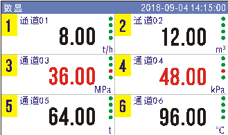
Digital display interface
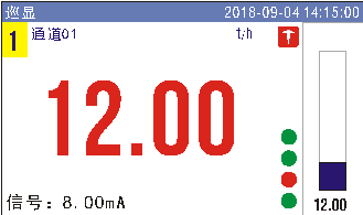
Patrol interface
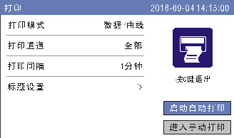
Print interface
Function Introduction
Universal signal input (isolated type)
The data logger is designed with a maximum of 6 universal signal input channels, supporting mV, V, mA, resistance thermometer, and thermocouple signals. The channel signal type is configured through input settings. The data logger automatically switches to the corresponding acquisition circuit based on the configured signal type, with a signal acquisition cycle of 1 second.
Each channel can be independently configured with parameters such as unit, range, decimal places, adjustment, filtering, open-circuit detection, and small signal suppression.
Data recording and alarming, power failure detection, and log recording.
The data logger records channel sampling data in real time according to the system configuration settings, with selectable recording intervals: 1 second, 2 seconds, 5 seconds, 10 seconds, 15 seconds, 30 seconds, 1 minute, 2 minutes, 5 minutes, 10 minutes, 30 minutes, and 1 hour. The data logger has 16MB of internal memory, capable of storing 900,000 records. With a 6-channel, 1-second recording interval, it can store data for 10 days; increasing the recording interval will correspondingly increase the recording period. The data logger also simultaneously records channel alarms, instrument power failures, and operation log information, with 256 records for each type, using a circular overwrite storage mode.
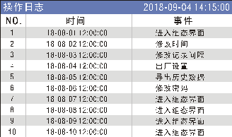
Operation Log
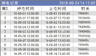
Power outage log
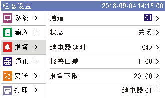
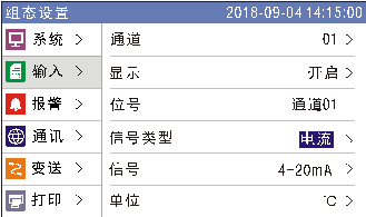
Configuration interface
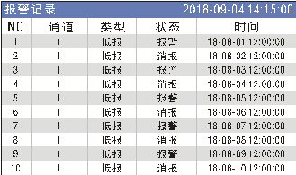
Alarm records
The data, curves, and records show...
The data recorder features a 4-inch high-definition color LCD screen with a resolution of 800*480 pixels. The recorder is designed with multiple data display options, including digital display, bar graphs, real-time curves, and a dashboard. It can display historical data such as historical curves, alarm lists, power failure records, and operation logs. The recorder is equipped with a bilingual system (Chinese and English) that can be switched between languages.
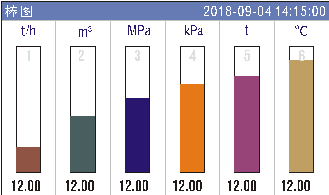
Bar chart interface
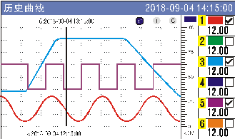
Historical trend chart
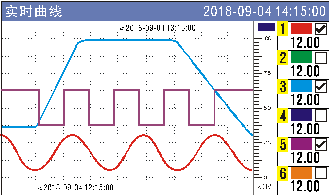
Real-time line graph
Alarm relay output
The recorder is designed with a maximum of 6 alarm relay outputs, and the relays are of the normally open type. Through alarm configuration settings, the relay contacts can be arbitrarily assigned to specific channels. Four types of alarms can be set: high alarm, low alarm, high-high alarm, and low-low alarm. Alarm hysteresis and relay delay parameters can also be configured.
24VDC sensor power distribution
The data logger is configured with two 24VDC power supply outputs for powering sensors. It can directly drive two-wire sensors, with the current loop connected in series with the data logger’s input channel.
4-20mA transmitter output
The data logger can be optionally equipped with up to two 4-20mA transmitter output channels, and the transmission relationship between the output and input channels can be configured through the output configuration settings.
RS485 communication interface
The data logger is equipped with one RS485 communication interface, using the standard MODBUS RTU communication protocol in slave mode, enabling external data communication and transmission. It supports real-time channel data and channel alarm status data, and provides 32-bit integer and 32-bit floating-point data types. The communication baud rate and byte order are configurable.
Miniature printer interface
An optional miniature printer interface is available, enabling automatic real-time printing of data and curves, as well as manual printing of historical data and curves.
USB data backup
The data logger is equipped with a USB 2.0 interface, allowing for manual export of historical data to a USB flash drive via the USB port, and automatic scheduled backup of historical data.
Automatic printing interface
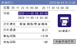
Manual printing interface
Configuration import and firmware update
It supports importing and exporting configuration parameters and updating instrument firmware via the USB interface.
Cumulative flow rate (without temperature and pressure compensation)
The data logger supports channel flow accumulation but does not have temperature and pressure compensation functions.
Vacuum level calculation algorithm
The data logger supports channel vacuum level algorithms, and, in conjunction with the vacuum gauge output signal, calculates, stores, and displays data in terms of vacuum level.
Upper-level computer data management software
The data logger comes with accompanying PC-based data management software, which supports viewing and exporting data from USB drives, and also supports real-time data monitoring on a single computer. It supports both graphical and tabular data display modes and can export data to Excel reports.
Core technical parameters
Hardware Specifications: 4-inch 800-dot full-color LCD screen; 128MB memory, capable of storing 900,000 historical records; equipped with high-speed USB2.0, RS485 (supports Modbus RTU protocol), and RJ45 interfaces; standard 2-channel relay output, 2-channel DC 24V power distribution, and 2-channel 4-20mA transmitter output (load <750Ω).
Measurement Specifications: 6-channel fully isolated universal analog input, supporting 2-channel frequency signal input (0Hz~10000Hz, accuracy 1Hz); compatible with various signals including current (0-10mA, 4-20mA, etc.), voltage (0-5V, 1-5V, 0-20mV, etc.), resistance thermometers (Pt100, Cu50, Cu53), and thermocouples (12 types including K, S, B, etc.); high measurement accuracy, analog signal accuracy ±0.2% F.S., temperature signal accuracy ±0.5~3℃, sampling period 1 second.
Installation and Environmental Parameters: Indoor panel-mounted installation, panel dimensions 160x80mm, opening size 152x76mm, panel thickness suitable for 2-5mm; device weight 450 grams; operating temperature -10~60℃, humidity 0~85% RH (non-condensing), 30-minute warm-up required after power-on.
Operation and Function Modules
- Key Operation Logic: Left and right keys are used to switch display screens, turn pages, or move the cursor; up and down keys are used to switch menu items, channels, or functions; the Enter key is used to confirm, enter submenus, or execute operations; the Cancel key is used to return, cancel the current operation, or delete text.
Display and Query Functions: Supports multi-interface switching including digital display, single channel, bar graph, real-time curve, and historical curve; can query 256 power-off records, 256 alarm records, and 256 system logs; historical curves support 1/2/4/8 times zoom, and specified channel curves can be hidden or displayed.
Data Transmission and PC Software: Inserting a USB flash drive automatically enters the data transmission interface; exported data includes historical data, power-off records, alarm records, and operation logs; files are named by date (e.g., 180904A.PLR) and stored in the PLR folder in the root directory of the USB flash drive; the exported file needs to be opened with the PC software PLR.EXE, which can be obtained from the data logger.
Configuration Settings System: The initial configuration password is 0000; supports system configuration (time, language, recording interval, etc.), input configuration (signal type, unit, range, etc.), alarm configuration (alarm threshold, relay delay, etc.), communication configuration (address, baud rate, etc.), transmitter configuration, and printing configuration; supports factory reset, after which parameters are reset to default values (e.g., signal is 4-20mA, recording interval is 5 seconds, etc.).
Alarm Function Details: 6 normally open relay alarm outputs, supporting four levels of alarms: low (LO), high (HI), low-low (LL), and high-high (HH); a 0-60 second relay delay can be set to avoid false triggers; supports alarm hysteresis setting to prevent frequent alarm fluctuations when the value is close to the alarm threshold.
Product Advantages
- Hardware configuration adapted to industrial needs: The 6-channel fully isolated design prevents signal interference and ensures measurement accuracy, meeting the needs of multi-parameter synchronous monitoring in industrial scenarios; 128Mb large-capacity memory can store 900,000 records, satisfying long-term data retention requirements; abundant interfaces (USB, RS485, RJ45) support rapid data export and remote communication, compatible with industrial automation system integration.
Functional design balances practicality and flexibility: Multiple interface display modes meet observation needs in different scenarios (e.g., digital display/curve for real-time monitoring, historical curves for data review); four-level alarm mechanism with relay delay and hysteresis settings allows for precise early warning based on actual needs, reducing false alarms; full-dimensional configuration functions support users to customize parameters according to specific application scenarios, adapting to different signal types, measurement ranges, and communication protocols.
High ease of operation and maintenance: Clear button logic and intuitive interface switching allow for easy operation without professional training; one-click data export via USB drive simplifies the data transfer process, and PC software supports subsequent data analysis; the targeted troubleshooting guide quickly identifies common problems, reducing operation and maintenance costs.
Applicable scenario positioning
With its multi-channel, high-precision, and large-capacity storage capabilities, this device is suitable for various industrial fields such as chemical, power, metallurgy, and pharmaceutical industries. It can be used for continuous monitoring and data recording of various physical quantities such as temperature, pressure, flow rate, and liquid level. It is particularly suitable for scenarios requiring long-term storage of monitoring data, trend analysis, or anomaly detection, making it an important data acquisition and recording terminal in industrial automation monitoring systems.