GT71R Data logger
GT71R Paperless Recorder
This recorder is a highly integrated, full-featured, user-friendly, reliable, and ultimately ideal product. Our company’s ultra-thin, wide-screen paperless recorder is designed to meet the needs of instrument users and enhance their user experience. It primarily targets various industries including petroleum and petrochemicals, chemical engineering, papermaking, textile printing and dyeing, metallurgy and building materials, science and education, medical care, municipal environmental protection, energy metering, food and beverages, equipment manufacturing, equipment sets, and agriculture, forestry, animal husbandry, and fisheries.
Product Features
Supports touch functionality (optional feature)
Supports dual communication functionality (optional feature)
Supports timed printing functionality (optional feature)
Supports DC power supply (optional feature)
Supports custom label numbering and units (optional feature)
Supports Ethernet communication (custom feature)
Supports communication data acquisition (custom feature)
Supports power output (optional feature)
Supports transmitter output function (optional)
Supports alarm output function (optional)
Supports PID control function (optional)
Supports manual serial port printing function (optional)
Supports standard serial communication function (optional)
Supports flow accumulation and temperature/pressure compensation functions (optional)
Data logging/transmission and backup functions (standard)
Universal analog input (standard)
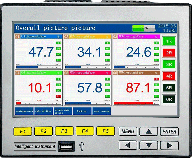
Product application interface
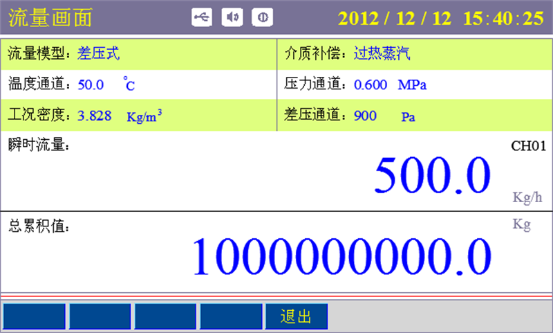
Traffic data screen
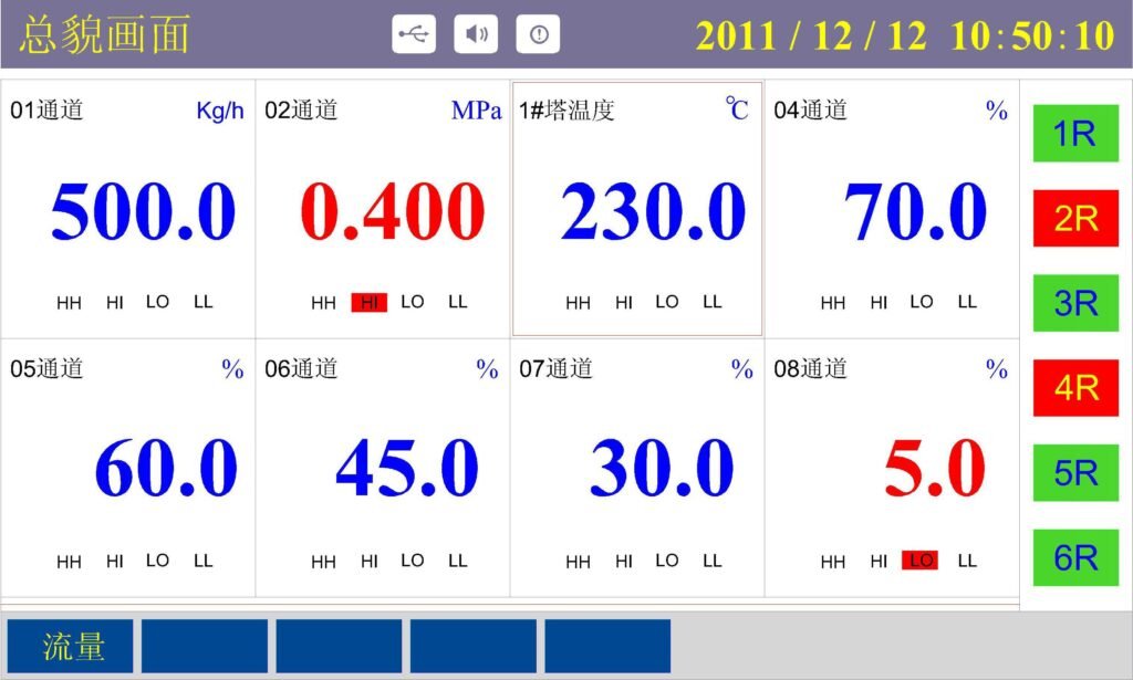
Product Overview and Applicable Scenarios
Core Positioning: Developed to address the pain points of traditional recorders, such as insufficient installation depth, limited data acquisition channels, and poor user experience, this ultra-thin, wide-screen paperless recorder combines high integration, rich functionality, high reliability, and high efficiency. Its core value lies in meeting the sensing needs of industrial scenarios and enhancing the user experience.Applicable Industries: Widely applicable to various fields including petroleum, petrochemical, chemical, paper and plastics, textile printing and dyeing, metallurgy and building materials, science and education, national defense, biomedicine, municipal environmental protection, energy metering, food and oil, tobacco, equipment manufacturing, agriculture, forestry, animal husbandry, and fisheries, meeting diverse data monitoring needs in general industrial applications.
Standard Features: General analog input (up to 16 channels), data recording and backup, standard serial communication, USB data transfer (compatible with 1G-32GB industrial-grade USB drives), hardware power failure/clock protection.
Optional Features: Touch operation, dual communication modes, timed printing, DC power supply, PID control, flow accumulation temperature and pressure compensation, alarm output (up to 6 relay channels).Customizable Features: Communication stop, idle operation, communication acquisition, specific signal input (such as PT1000, digital input DI, pulse input PI), etc.
Detailed explanation of key technical parameters
| Category | Detailed Description |
| Display Module | 7-inch true-color TFT LCD real-time display, ±0.2% F.S.; playback accuracy ±0.2% F.S. |
| Input Channels | Supports up to 16 universal signal inputs |
| Input Types | Voltage input: 0-5V, 1-5V, 0-20mV, 0-100mV Current input: 0-10mA, 4-20mA, 0-20mA |
| Resistance input: Res Thermocouple: PT100/Cu50/G53/Cu100/BA1/BA2 | |
| Thermocouple: S, B, K, T, R, E, N, J | |
| Radiation thermometer: Fl, F2 | |
| Tungsten-rhenium: WRe3-25, WRe5-26 Other signal inputs require customization (e.g., D1/P1, etc.) | |
| Outputs | Power distribution output: Supports 3 sets of isolated power distribution +24VDC, 60mA per set, also supports 12VDC and 5VDC power distribution |
| Transmitter output: Supports 4 channels of standard 4-20mA current transmitter output | |
| Convenient for display instruments or DCS/PLC data acquisition, enabling long-distance signal transmission | |
| Relay alarm output: Supports up to 6 relay alarms, contact capacity 1A@250VAC/1A@30VDC | |
| Configurable upper limit, upper limit, lower limit, and lower limit alarms | |
| processor | High-performance ARM Cortex-M3 32-bit RISC core for multi-channel signal acquisition, recording, display, and alarming |
| Storage module | Large-capacity parallel NAND FLASH memory chip for storing historical data, serial FRAM memory chip for storing parameter information |
| Communication and printing | Communication interface: RS232C and RS485 communication interfaces, supporting Modbus RTU Protocol |
| Ethernet Interface: Standard RJ-45 Ethernet interface | |
| Printing Interface: RS232C direct connection to a miniature printer, baud rate 1200 | |
| Recording function | Recording Capacity: 64/128/192/248MB (FLASH capacity selectable) |
| Recording Interval: 1 second to 240 seconds, 11 selectable intervals: 1/2/4/8/12/24/36/60/120/180/240 seconds | |
| Recording Time: The recording time depends on the FLASH memory capacity, number of input points, and recording interval. The formula is as follows: | |
| (The units of the values substituted must be consistent with those in the formula) Recording Days = FLASH Capacity (MB) x 1024 x 1024 x Recording Interval (seconds) / Number of Channels x 16 x 24 x 3600 | |
| Data Transfer | Data Backup and Transfer: Supports USB 1.1 and 2.0 flash drives, supports 1G to 32G USB drives for data transfer |
| Power Supply | Power Supply: 100~240VAC (rated voltage 220VAC), 50/60HZ AC power supply, supports 24VDC power supply |
| Protection Features | Power Failure Protection: Built-in memory protects parameters and historical data, permanently saved after power failure |
| Clock Protection: Integrated hardware clock, operates accurately even after power failure | |
| Operating Environment | Temperature: 0~50°C (avoid direct sunlight) Relative Humidity: 0~85% R.H (non-condensing) Altitude: <2000m |
Display and Accuracy: 7-inch true-color TFT LCD screen (800×480 pixels), real-time display accuracy ±0.2% FS, playback accuracy ±0.2% FS (cold junction compensation required for thermocouples), cold junction compensation accuracy ±2℃, clock accuracy ±2 seconds/day.
Hardware Configuration:
Processor: Upgraded ARM Cortex-M3 32-bit RISC core, supporting synchronous acquisition, recording, display, and alarm of multiple signals.
Storage: Large-capacity NAND flash memory (optional 64/128/192/248MB) for historical data, serial FRAM memory for storing configuration parameters and other critical information.
Input and Output Specifications:
Input: Fully isolated universal input, supporting voltage (0-5V, 1-5V, etc.), current (0-10mA, 4-20mA, etc.), resistance (0-400Ω), resistance thermometers (PT100, Cu50, etc., three-wire system, welding resistance <10Ω), thermocouples (S, B, K, etc.), radiation pyrometers (F1, F2), tungsten-rhenium thermocouples, and other signals.
Output: Up to 3 channels of 24VDC isolated output (≤60mA per channel), up to 4 channels of standard current output (maximum load capacity 750Ω), up to 6 channels of relay output alarms (contact capacity 1A@250VAC/1A@30VDC, customizable).
Communication and Printing:
Communication Interface: RS232C, RS485 (supports simultaneous use), compatible with Modbus RTU protocol, selectable baud rates 1200/4800/9600, etc.
Printing Interface: RS232C direct connection to a miniature printer, baud rate 1200.
Environment and Power:
Operating Environment: Temperature 0-50℃ (avoid direct sunlight), relative humidity 0-85%RH (non-condensing), altitude <2000m; not for use in environments with paint, flammable and explosive materials, dust, strong vibration, or strong electromagnetic interference. Power Supply: AC 100-240V (rated 220V, 50/60Hz), DC 24V (18-36VDC), DC 12V (9-18VDC, specify when ordering).
Recording Performance: Recording interval 1-240 seconds (11 selectable intervals). The number of recording days depends on the FLASH storage capacity, the number of input points, and the recording interval. The calculation formula is: Recording days = (FLASH storage capacity (MB) × 1024 × 1024 × recording interval (seconds)) / (number of channels × 16 × 24 × 3600).
Data analysis interface
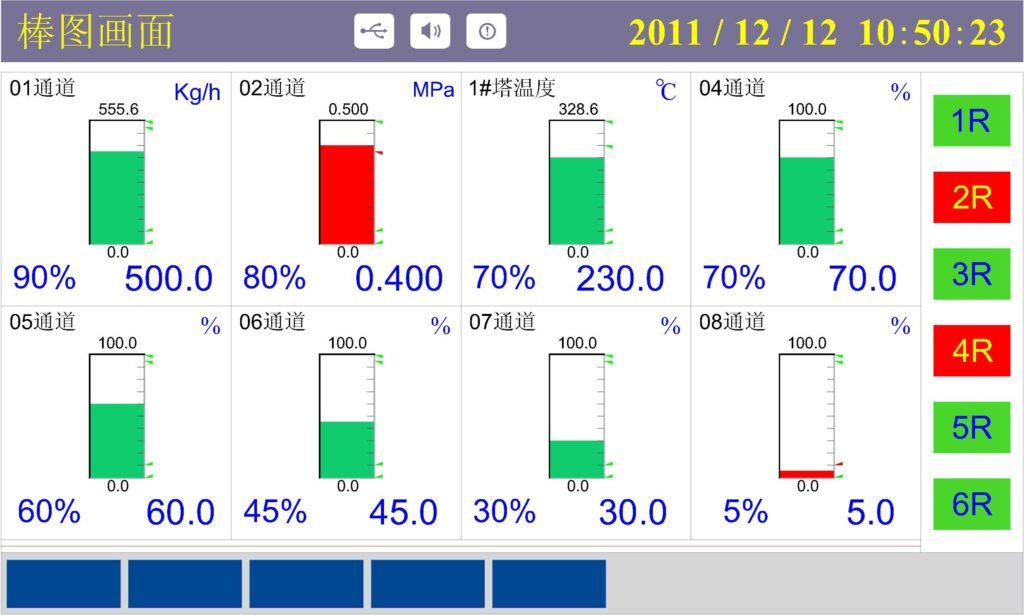
Bar chart data analysis interface
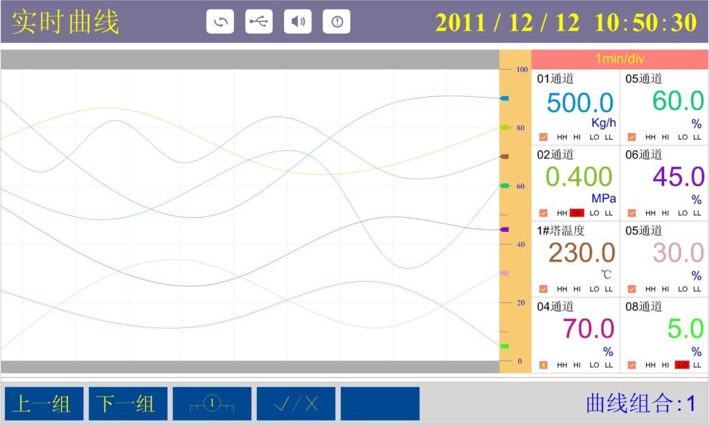
Real-time curve graph data analysis interface
Installation and Wiring Specifications
Installation Panel: Steel plate with a thickness of 1.5-4.0mm, installed horizontally (slight adjustment is acceptable, but tilting is prohibited). Ensure sufficient space for material handling during installation and removal.
Environmental Restrictions: Indoor installation, well-ventilated environment. Avoid exposure to wind, rain, direct sunlight, high temperature and humidity, corrosive gases, short circuits, and liquid splashes. Take precautionary measures when near power lines, strong inverters, or strong magnetic fields.
Wiring Specifications:
General Requirements: Disconnect power before wiring. Use U-shaped voltage terminals with insulation sleeves (M3 screws), and tighten terminal screws to a torque of 0.5 Nm. An air switch must be installed in the power circuit. Power lines and signal lines should be laid separately. Use shielded signal lines to prevent electrostatic interference, and ensure proper grounding to prevent electromagnetic induction interference.
Special Wiring:
Power Wiring: AC/DC input must match the instrument’s specifications, and the voltage must be within the rated range.
Signal Wiring: Thermoresistors require three copper wires of the same specification (resistance < 10Ω). Avoid using thick wires with good conductivity for thermocouples, and avoid significant temperature fluctuations in the surrounding environment. Specific requirements for digital signals, PT1000, etc., should be described during ordering.
Communication Wiring: RS485 uses shielded twisted-pair cable (up to 1000m), and a 120Ω termination resistor must be connected at the end. RS232C cable length should not exceed 10m, and hot-plugging is prohibited.
Relay Output: Use double-insulated wires, with a cross-sectional area of ≥0.5mm². Normally open contacts are the default; normally closed or high-contact-capacity contacts must be specified when ordering.
Operation and configuration process
Grouping interface
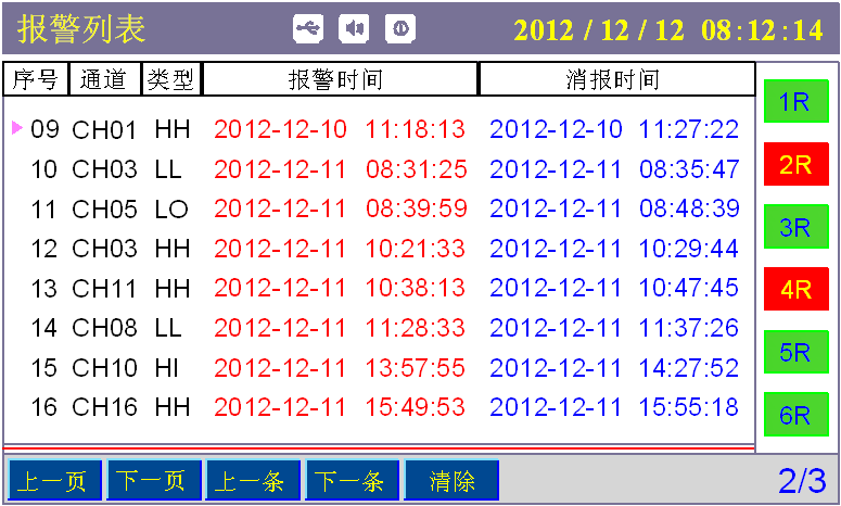
Alarm interface
Operating Modes and Button Functions:
Mode Classification: Operating mode (default upon power-on, includes data display and inquiry) and Configuration mode (accessed by pressing and holding the MENU + ENTER keys for more than 1 second, requires password entry).
Button Functions: MENU key switches the main page, arrow keys switch channels/move position/adjust values, ENTER key confirms/executes functions, F1-F5 keys correspond to on-screen soft key functions; the combination key MENU + ENTER enters configuration mode; pressing and holding specific keys enables various quick operations.
Core Operation Screens:
Main Screen: Displays up to 16 channels of real-time data on a single screen, including channel number, tag number, real-time value, percentage, bar graph, unit, relay status, alarm status, etc., supports quick switching to configuration, flow, grouping, backup, and bar graph screens.
Screens: Bar graph screen (displays 16 channels of bar graph data), real-time/historical curve screen (up to 8 records per screen, supports zooming, showing/hiding curves), PID screen (single-loop parameter display and adjustment), alarm/power-off list (up to 12 records per screen, supports inquiry and sorting).
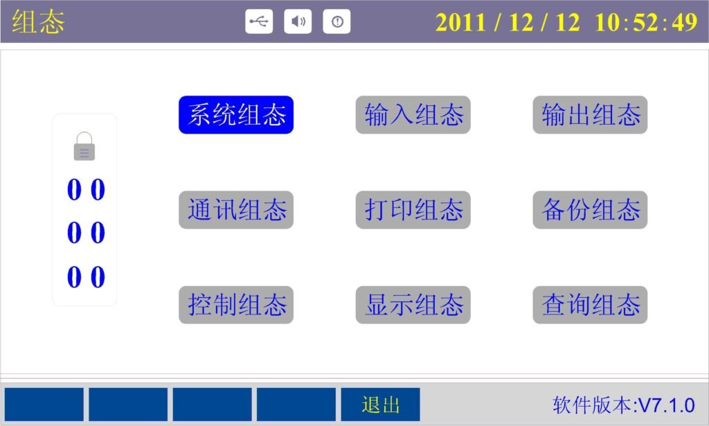
Configuration Process and Permissions:
Permission Management: Divided into Operator (default password 000000, can only configure input, backup, and printing) and Administrator (default password 100000, full configuration access). It is recommended to change the password after purchase and keep it secure.
Core Configuration Items:
System Configuration: Set time and date, recording interval, key sound, automatic switching time, PID parameter adjustment permissions, system maintenance (clear power-off/alarm list, restore factory settings, irreversible).
Input Configuration: Select signal type, range limits, engineering units, analog time, cold junction compensation mode, signal clipping, linear adjustment, supports flow accumulation and alarm parameter sub-configuration, allows copying and pasting channel parameters.
Output Configuration: Set output type, signal source, range limits, positive/negative action, etc.
Communication/Printing/Backup Configuration: Communication mode (PC/printer), address, baud rate; printing channels, type, interval, range; backup channels, time range, U disk status monitoring. Display/Control Configuration: Display combinations (up to 6 groups, 8 channels per group), startup screen, curve colors; PID loop parameters (proportional P, integral I, derivative D, setpoint SV, process value PV, output value MV, etc.).
Auxiliary Functions: Report inquiry (shift reports, daily reports, monthly accumulated data), function information viewing (system configuration, module quantity, software version), auxiliary interface (quick setting of alarm values, range, etc.).